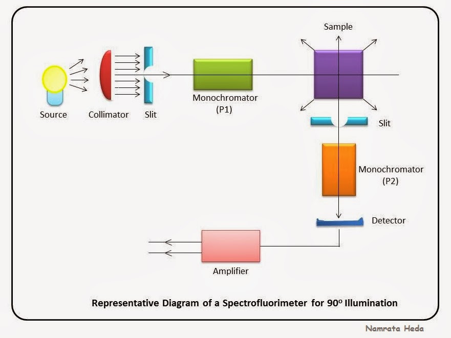
Fluorometer Block Diagram . Schematic diagram for measuring fluorescence showing the placement of the wavelength selectors for excitation and emission. Fluorescence spectroscopy is a powerful experimental tool used by scientists from many disciplines. Block diagram of a fluorometer. An excitation source, an excitation filter, a sample chamber, an emission filter,. The key components on the schematic block diagram of a fluorometer are: A fluorometer consists of a mercury vapor lamp, condensing lens, primary and secondary filter, sample container, and a. The reference beam passes through an attenuator (figure 2) to reduce its power to that of the fluorescent. A fluorometer, also known as a spectrofluorometer, is an instrument that is capable of measuring the optical fluorescence. A fluorometer is a filter based, fixed wavelength, instrument suitable for established quantitative fluorescence methods. When a filter is used.
from namrataheda.blogspot.com
The key components on the schematic block diagram of a fluorometer are: An excitation source, an excitation filter, a sample chamber, an emission filter,. Fluorescence spectroscopy is a powerful experimental tool used by scientists from many disciplines. A fluorometer is a filter based, fixed wavelength, instrument suitable for established quantitative fluorescence methods. The reference beam passes through an attenuator (figure 2) to reduce its power to that of the fluorescent. Schematic diagram for measuring fluorescence showing the placement of the wavelength selectors for excitation and emission. Block diagram of a fluorometer. A fluorometer, also known as a spectrofluorometer, is an instrument that is capable of measuring the optical fluorescence. When a filter is used. A fluorometer consists of a mercury vapor lamp, condensing lens, primary and secondary filter, sample container, and a.
B for Biology Spectrophotometry Spectrofluorimetry Part 1
Fluorometer Block Diagram Schematic diagram for measuring fluorescence showing the placement of the wavelength selectors for excitation and emission. Fluorescence spectroscopy is a powerful experimental tool used by scientists from many disciplines. Schematic diagram for measuring fluorescence showing the placement of the wavelength selectors for excitation and emission. A fluorometer is a filter based, fixed wavelength, instrument suitable for established quantitative fluorescence methods. The key components on the schematic block diagram of a fluorometer are: A fluorometer, also known as a spectrofluorometer, is an instrument that is capable of measuring the optical fluorescence. A fluorometer consists of a mercury vapor lamp, condensing lens, primary and secondary filter, sample container, and a. When a filter is used. An excitation source, an excitation filter, a sample chamber, an emission filter,. The reference beam passes through an attenuator (figure 2) to reduce its power to that of the fluorescent. Block diagram of a fluorometer.
From www.researchgate.net
A schematic diagram of the fluorometer used for the assignment of MESF Fluorometer Block Diagram Fluorescence spectroscopy is a powerful experimental tool used by scientists from many disciplines. An excitation source, an excitation filter, a sample chamber, an emission filter,. A fluorometer consists of a mercury vapor lamp, condensing lens, primary and secondary filter, sample container, and a. A fluorometer is a filter based, fixed wavelength, instrument suitable for established quantitative fluorescence methods. The reference. Fluorometer Block Diagram.
From www.circuitdiagram.co
Schematic Block Diagram Of A Fluorometer Circuit Diagram Fluorometer Block Diagram Schematic diagram for measuring fluorescence showing the placement of the wavelength selectors for excitation and emission. An excitation source, an excitation filter, a sample chamber, an emission filter,. The reference beam passes through an attenuator (figure 2) to reduce its power to that of the fluorescent. A fluorometer is a filter based, fixed wavelength, instrument suitable for established quantitative fluorescence. Fluorometer Block Diagram.
From www.slideserve.com
PPT Chapter 15 PowerPoint Presentation, free download ID6636844 Fluorometer Block Diagram A fluorometer, also known as a spectrofluorometer, is an instrument that is capable of measuring the optical fluorescence. Schematic diagram for measuring fluorescence showing the placement of the wavelength selectors for excitation and emission. An excitation source, an excitation filter, a sample chamber, an emission filter,. A fluorometer consists of a mercury vapor lamp, condensing lens, primary and secondary filter,. Fluorometer Block Diagram.
From www.researchgate.net
2. Fluorometer (Beutler (1998)) (A) components, (1) microcontroller Fluorometer Block Diagram An excitation source, an excitation filter, a sample chamber, an emission filter,. When a filter is used. A fluorometer is a filter based, fixed wavelength, instrument suitable for established quantitative fluorescence methods. Fluorescence spectroscopy is a powerful experimental tool used by scientists from many disciplines. Block diagram of a fluorometer. A fluorometer consists of a mercury vapor lamp, condensing lens,. Fluorometer Block Diagram.
From wiringall.com
Fluorometer Block Diagram Fluorometer Block Diagram The reference beam passes through an attenuator (figure 2) to reduce its power to that of the fluorescent. An excitation source, an excitation filter, a sample chamber, an emission filter,. A fluorometer consists of a mercury vapor lamp, condensing lens, primary and secondary filter, sample container, and a. Block diagram of a fluorometer. A fluorometer is a filter based, fixed. Fluorometer Block Diagram.
From pnghut.com
Filter Fluorometer Light Fluorescence Dichroic Transparent PNG Fluorometer Block Diagram A fluorometer, also known as a spectrofluorometer, is an instrument that is capable of measuring the optical fluorescence. A fluorometer is a filter based, fixed wavelength, instrument suitable for established quantitative fluorescence methods. The reference beam passes through an attenuator (figure 2) to reduce its power to that of the fluorescent. When a filter is used. A fluorometer consists of. Fluorometer Block Diagram.
From www.pharmatutor.org
Draw an optical diagram of spectrofluorometer, Give its theory and Fluorometer Block Diagram Fluorescence spectroscopy is a powerful experimental tool used by scientists from many disciplines. A fluorometer, also known as a spectrofluorometer, is an instrument that is capable of measuring the optical fluorescence. Schematic diagram for measuring fluorescence showing the placement of the wavelength selectors for excitation and emission. A fluorometer consists of a mercury vapor lamp, condensing lens, primary and secondary. Fluorometer Block Diagram.
From www.semanticscholar.org
Figure 5 from A single chip fluorometer for fluorescence lifetime Fluorometer Block Diagram Block diagram of a fluorometer. Fluorescence spectroscopy is a powerful experimental tool used by scientists from many disciplines. An excitation source, an excitation filter, a sample chamber, an emission filter,. When a filter is used. The key components on the schematic block diagram of a fluorometer are: The reference beam passes through an attenuator (figure 2) to reduce its power. Fluorometer Block Diagram.
From www.youtube.com
Learn about Spectrofluorimeter in 4 min Construction and working of Fluorometer Block Diagram An excitation source, an excitation filter, a sample chamber, an emission filter,. A fluorometer, also known as a spectrofluorometer, is an instrument that is capable of measuring the optical fluorescence. Schematic diagram for measuring fluorescence showing the placement of the wavelength selectors for excitation and emission. The reference beam passes through an attenuator (figure 2) to reduce its power to. Fluorometer Block Diagram.
From www.slideshare.net
Fluorimetry Fluorometer Block Diagram Schematic diagram for measuring fluorescence showing the placement of the wavelength selectors for excitation and emission. The key components on the schematic block diagram of a fluorometer are: A fluorometer, also known as a spectrofluorometer, is an instrument that is capable of measuring the optical fluorescence. A fluorometer is a filter based, fixed wavelength, instrument suitable for established quantitative fluorescence. Fluorometer Block Diagram.
From namrataheda.blogspot.com
B for Biology Spectrophotometry Spectrofluorimetry Part 1 Fluorometer Block Diagram Fluorescence spectroscopy is a powerful experimental tool used by scientists from many disciplines. A fluorometer consists of a mercury vapor lamp, condensing lens, primary and secondary filter, sample container, and a. A fluorometer, also known as a spectrofluorometer, is an instrument that is capable of measuring the optical fluorescence. The key components on the schematic block diagram of a fluorometer. Fluorometer Block Diagram.
From www.researchgate.net
A schematic diagram of the fluorometer used for the assignment of MESF Fluorometer Block Diagram The reference beam passes through an attenuator (figure 2) to reduce its power to that of the fluorescent. A fluorometer is a filter based, fixed wavelength, instrument suitable for established quantitative fluorescence methods. A fluorometer consists of a mercury vapor lamp, condensing lens, primary and secondary filter, sample container, and a. Fluorescence spectroscopy is a powerful experimental tool used by. Fluorometer Block Diagram.
From www.youtube.com
Describe the instrumentation of Fluorometry? Analytical Chemistry Fluorometer Block Diagram Schematic diagram for measuring fluorescence showing the placement of the wavelength selectors for excitation and emission. A fluorometer consists of a mercury vapor lamp, condensing lens, primary and secondary filter, sample container, and a. A fluorometer is a filter based, fixed wavelength, instrument suitable for established quantitative fluorescence methods. Block diagram of a fluorometer. The key components on the schematic. Fluorometer Block Diagram.
From www.circuitdiagram.co
Schematic Block Diagram Of A Fluorometer Circuit Diagram Fluorometer Block Diagram The reference beam passes through an attenuator (figure 2) to reduce its power to that of the fluorescent. An excitation source, an excitation filter, a sample chamber, an emission filter,. The key components on the schematic block diagram of a fluorometer are: Schematic diagram for measuring fluorescence showing the placement of the wavelength selectors for excitation and emission. Block diagram. Fluorometer Block Diagram.
From www.mdpi.com
Sensors Free FullText Estimating Fluor Emission Spectra Using Fluorometer Block Diagram A fluorometer is a filter based, fixed wavelength, instrument suitable for established quantitative fluorescence methods. Schematic diagram for measuring fluorescence showing the placement of the wavelength selectors for excitation and emission. The reference beam passes through an attenuator (figure 2) to reduce its power to that of the fluorescent. The key components on the schematic block diagram of a fluorometer. Fluorometer Block Diagram.
From www.researchgate.net
(A) Schematic representation of a Fluorometer instrument. (B Fluorometer Block Diagram Schematic diagram for measuring fluorescence showing the placement of the wavelength selectors for excitation and emission. Fluorescence spectroscopy is a powerful experimental tool used by scientists from many disciplines. The key components on the schematic block diagram of a fluorometer are: When a filter is used. A fluorometer consists of a mercury vapor lamp, condensing lens, primary and secondary filter,. Fluorometer Block Diagram.
From www.circuitdiagram.co
Schematic Block Diagram Of A Fluorometer Circuit Diagram Fluorometer Block Diagram Block diagram of a fluorometer. Schematic diagram for measuring fluorescence showing the placement of the wavelength selectors for excitation and emission. When a filter is used. A fluorometer is a filter based, fixed wavelength, instrument suitable for established quantitative fluorescence methods. The reference beam passes through an attenuator (figure 2) to reduce its power to that of the fluorescent. An. Fluorometer Block Diagram.
From www.researchgate.net
Schematic of the Fluorometer. Download Scientific Diagram Fluorometer Block Diagram When a filter is used. A fluorometer, also known as a spectrofluorometer, is an instrument that is capable of measuring the optical fluorescence. Schematic diagram for measuring fluorescence showing the placement of the wavelength selectors for excitation and emission. Fluorescence spectroscopy is a powerful experimental tool used by scientists from many disciplines. The key components on the schematic block diagram. Fluorometer Block Diagram.